RFM69 on CircuitPython

Tags

I am excited to see a library for the RFM69 for CircuitPython from Adafruit.  While I want to use LoRa, this library is a good start to a RadioHead port. 

The Goal

The goal of this post is to document the steps that got to a conversation between two Feather M0 RFM69’s using the new adafruit_RFM69.py library developed by Tony DiCola.  A “successful” conclusion has one RFM69 Feather sending packets while the other receives them.

Thanks to Those That Went Before

  • Tony Dicola for many things related to the projects I work on.  In particular for this post, Tony wrote the RFM69 for CircuitPython library.  I also enjoy his videos, like this one:  – MicroPython mpy-utils: Mount MicroPython board as filesystem and more with Tony D!  Clearly useful in understanding and using these tools within the CircuitPython workflow.  When I think of Tony, I think of an exceptionally gifted programmer who has the rare skills of being able to kindly teach and communicate.   
  • Adafruit – thank you for treating me – us – your customers – as people you care about.  The would would be AH-MAZ- ZING …if companies – especially the largest one – saw their shareholders as not only EVERYONE that works for them but also the customers.  Thank you for the great products.  Thank you for sharing your passion and knowledge.
  • @kattni @jerryn @cater @þeshipu @tonydi on Adafruit’s circuitpython discord channel.  I would not have been able to get this working without their help.  @cater pointed me to the location where there were mpy-cross utilities for the different platforms.  @kattni built me a version of mpy-cross that works on Mac Sierra since the version on the site.  @jerryn provided me with a build of CircuitPython that accepted pin settings for CS and RST.

Open Source

The Adafruit team is constantly evolving Circuit Python.  There seems to be new goodies at about once a month.  The latest release as I write this post is CircuitPython 2.2.1.  What is a YIPPEE! moment regarding this release is the inclusion of CircuitPython build for the RFM69 Feather and RFM8Z Feather.  I’m using the RFM69 Feather for now because it appears to be the one Tony works and tests on first.  Besides, the GitHub readme notes: 


The files I used for this post are located in my CircuitPythonRadio GitHub repository.

  • lib contains the .mpy library files that need to be copied to the /lib folder on the Feather.
  • lib_extra contains the mpy-cross utility @kattni built for me that runs on Mac Sierra.  Also, adafruit_rfm69.py is in this folder since I created a .mpy from this file.  Adafruit had the adafruit_rfm69.py library posted at this GitHub location.
  • Python contains:
    • The simpltest.py Tony wrote to test the adafruit_rfm69.py library 
    • send.py and receive.py – a riff on Tony’s example to keep sending packets.  I found it simpler to have one script whose job was solely to send packets and another whose job was to receive packets.  I copied send.py to one of the Feathers and renamed it main.py .  Similarly, I copied receive.py to the other Feather and renamed it main.py. 
    • Remove_comments_adafruit_rfm69.py I wrote to practice regular expressions.  I thought I might be able to remove all comments and then get to a file size that was equivalent to a .mpy.  Alas, I got to 15KB.  The .mpy is 10KB.  However, the more practice I can get with regular expressions is a “good thing” for me because they certainly come in handy…I just know, know, know in the future I will want to whip out my bag-oh-regular expression tricks…but for now…my knowledge will stay minimal and my use at this moment will remain dormant.

CircuitPython + Atom

It is best to use a code editor when working with Circuit Python.  On the mac, the Finder and text editors will bloat away any space on the Feather with backup, indexing files, etc….stuff that isn’t needed for Circuit Python.  The other reason is it can simplify running and debugging code.  My code editor of choice is Atom.

Tony talks about this in his video: CircuitPython & macOS: Getting Started and Editing Files with Tony D!  It’s worth a watch if you are not familiar with CircuitPython + Atom workflow.

Install the software

I use a Mac.  The steps I used include:

  • Install the RFM69 Feather version of circuit python.  At the time I was trying out the library, there was no RFM Feather CircuitPython bin.  Lucky for me, the most kind @jerryn sent me feather_m0_rfm69_firmware.bin.  I used BOSSA to install onto the Feather, erasing all files.  Don’t forget to click the reset button twice to get into boot loader mode. 
  • After installation, restart the Feather by clicking the reset button once.
  • (Maybe in the future a lack space will be less of an issue…for now…)  Maximize the amount of space for code on the Feather M0 by following the instructions given in  “welcome-to-circuitpython.pdf.” From the doc:
——————————————————————————————-

Mac OSX loves to add extra files.  Luckily you can disable some of the extra hidden files that Mac OSX adds by running a few commands to disable search indexing and create zero byte placeholders.

ls -l /Volumes 

Look for a volume with a name like CIRCUITPY (the default for CircuitPython). The full path to the volume is the /Volumes/CIRCUITPY path.  Now follow these handy-dandy-not-easy-to-remember steps:

mdutil -i off /Volumes/CIRCUITPY

cd /Volumes/CIRCUITPY

rm -rf .{,_.}{fseventsd,Spotlight-V*,Trashes}

mkdir .fseventsd

touch .fseventsd/no_log .metadata_never_index .Trashes

Now let’s never use the finder….and not forget to use the easy-to-forget command.  The doc goes on to caution: …you need to be careful to copy files to the board with a special command that prevents future hidden files from being created…

cp -X foo.mpy /Volumes/CIRCUITPY

cp -rX folder_to_copy /Volumes/CIRCUITPY

we’ll also want to check out how much space there is on the CIRCUITPYTHON volume with the df command.

——————————————————————————————-

  • Compress adafruit_rfm69.py from 33KB to adafruit_rfm69.mpy which will end up being 10KB.  If I didn’t do this, I ran out of memory.
    • GOTCHA: I had a vague idea what a mpy file was all about.  But…bummer…in Tony’s post he notes that mpy-cross runs on Vagrant.  Sadly, I installed/uninstalled Vagrant…great stuff…but a level of complexity I wanted to avoid.
      • @cater sent me a message on Adafruit/discord/circuitpython that the circuitpython builds included mpy-cross builds.  OOH!! Excitedly download mpy-cross-2.2.0-macos-high-sierra.  I am running Sierra on my Mac.  Unfortunately, despite help I gratefully received from the discord channel, I could not get mpy-cross to run on my Mac. @kattni jumped in and very kindly built me a version of mpy-cross that runs on Sierra.
      • go to a terminal window, get the file paths right (as needed):
        • $ ./mpy-cross adafruit_rfm69.py
  • Make a /lib folder on the Feather:  CIRCUITPY margaret$ mkdir lib
  • Copy adafruit_rfm69.mpy and BusDevice folder into the /lib folder.  This way we can use one copy command to copy the libraries into the Feather’s /lib folder.  Use -X and -r as noted above. 

Run Code

After copying the python libraries (adafruit_rfm69.mpy and the adafruit_bus_device folder) to the CIRCUITPY volume’s lib folder, i.e.: /Volumes/CIRCUITPY/lib, I used the Atom editor to copy send.py on one of the Feathers and receive.py on the other.  Both were then renamed main.py.

Note the pin settings:

CS = digitalio.DigitalInOut(board.RFM69_CS)

RESET = digitalio.DigitalInOut(board.RFM69_RST)

I then opened two screens, one for each of the Feathers:

NewImage

and YIPPEE!!! RFM69 packets whizzed between the sending Feather and the receiving Feather….

Notes from Along the Way

I put stuff here that I thought was worth sharing and remembering…at least documenting somewhere in the somewhat doubtful attempt I’ll be able to find in the future.

Kill Process

Sometimes the serial port continues to run even after I closed down the window.  When that happens, I close the process by doing the following in a terminal window:

$ lsof | grep /dev/tty.usbmodem1421

This gives me the process number:


screen    2451 margaret    5u      CHR              20,10    0t2103     1457 /dev/tty.usbmodem1421

I can then kill it:


$ kill 2451


Tried -> Not Useful

I originally tried to simplify the file copy workflow by using mpy-fuse to mount the Feather’s storage as a drive on Finder.  This generates errors most likely because I turn off indexing (and other?) goo that Finder wants to put on a storage device.  I’m sticking to ampy for file operations.  

Steps I took setting up mpy-fuse:

  • Install  Fuse.  I had done this when I was starting out programming on a Raspberry Pi.  Fuse extends the MacOS file system to devices like the Feather and Raspberry Pi that have a different file system than what is native on the Mac OS.
  • Install the mpy-utils, The utilities includes may-fuse.  I used pip within Terminal:
——————————————————————————————————————————————————————-

pip install mpy-utils Tony talks about needing sudo. However, just pip worked for me. This is most likely because I am not using the default Python that comes on a Mac. The version of Python I am using is Python 3.6.1 |Anaconda custom (x86_64)| (default, May 11 2017, 13:04:09) check the install:

mpy-fuse — help

——————————————————————————————-

——————————————————————————————————————————————————————–

mpy-fuse –port /dev/tty.usbmodem1421 –baud 115200 /Users/margaret/feather_board

Now I can see the Feather as a drive:
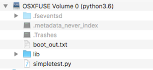
 

NewImage


Using Ajax to get to Energy Readings Stored on Raspberry Pi

Tags

, , , , , , ,

The project I am working on uses a browser page – I am developing on the Chrome browser as the client interface and Flask/Python on the Raspberry Pi to communicate with the browser and connect with readings coming in from sensors.  I am coding the browser code in JQuery and using ajax to talk to Flask.

Technologies this blog post assumes some familiarity – and I bumbled around the last couple of months learning – include:

  • HTML
  • JQuery
  • ajax
  • Flask
  • Python
OOH!!! YIPPEE!! SO MUCH TO LEARN!!!!
 
So here I am, trying to figure out why my calls to ajax keep failing.  Geez.  I’m googling for the answer, trying to follow Stack Overflow Q&A’s…but I’m still having difficulty.  What do I do?  Well, first I stop.  Then do Yoga…ah…much better.
 
Guess what I found out?  There is this  Postman app that is a very sweet way to understand and debug ajax <-> Flask interactions.  I wrote a simple Flask app that helped me understand:
  • how to just get data from the server app using GET
  • how to pass input into the server app using PUT

Flask App

from flask import Flask, render_template, jsonify, request

import datetime

app = Flask(__name__)


@app.route(‘/’)

def test():

    return jsonify({‘message’ :’It works! ‘})

@app.route(‘/posttest’,methods=[‘POST’])

def posttest():

    value = request.get_json();

    print(value[‘message’])

    return(value[‘message’]);

app.run(debug=True, host=’localhost’, port=9999)

I saved this file on the Raspberry Pi as app.py.  It has two routes, one for a GET, one for a POST.  I don’t explicitly state the GET method because by default Flask assumes it.  Also, I use debug=True so that changes I make in the code cause Flask to automatically update.  This means I don’t have to stop and then restart app.py.

Starting up the Flask app:

$ python app.py

 * Running on http://localhost:9999/ (Press CTRL+C to quit)

 * Restarting with stat

 * Debugger is active!

 * Debugger PIN: 115-663-274

Sometimes I’ve messed up stopping the Flask app when I close the terminal window.  This can happen – for example – when doing ctrl-z instead of ctrl-c:


OSError: [Errno 48] Address already in use

Googling around, I found I can release the Flask app by running.  Of course, changing the port from 9999 if I’m using a different one.

sudo lsof -i :9999 | grep “python” | cut -d ” ” -f2 | xargs kill -9

GET

Let’s start up the Postman app and do a GET route to the Flask app.  Doing a GET is easy-peasy.Pasted Image 1 8 18 3 38 AM
 
Type in localhost:9999 (the port the Flask app is listening on), make sure the big-ol-method button is set to GET, then hit SEND.
 
YIPPEE!!! – the Body returns the JSON sent from the Flask app:

@app.route(‘/’)

def test():

    return jsonify({‘message’ :’It works! ‘})

See the little code button?  When clicked, we get the JQuery code to copy/paste:

NewImage

The headers aren’t needed, so I remove them.

Post

The POST method is what we’re most interested in because we want to pass input into my Python app running on the Raspberry Pi.  

Flask Part

Here’s the Flask part of the test for handling a POST to the /posttest route:

@app.route(‘/posttest’,methods=[‘POST’])

def posttest():

    value = request.get_json();

    print(value[‘message’])

    return(value[‘message’]);

The key here is DO NOT FORGET to add methods=[‘POST’].

Postman Part

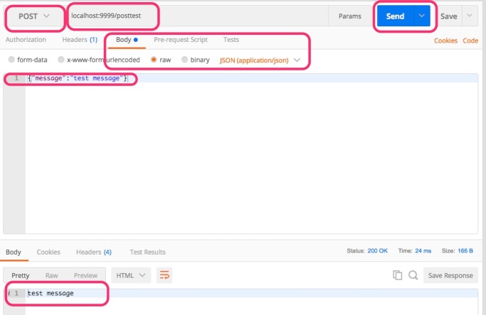
The Postman setup for Post is slightly more “complicated” than the GET because the Flask route assumes it is getting JSON: {“message”:”<some text>”}.  Note:  The POST will fail unless the value is a text string.  This is ok for passing JSON data since Javascript includes the JSON.stringify() function.

Pasted Image 1 8 18 4 43 AM

After changing the button that selects the operation to POST, the URL is changed to include the route to /posttest .  When the POST is selected, The Body radio button is available to let Postman know we will be sending JSON.  Finally, the JSON – formatted to what the /posttest route is expected in the Flask app – is typed in.  Hit the Send button. Notice the response area includes the text from the message.

Now let’s look at the code so we can figure out how to add this to our JQuery:

var settings = {

  “async”: true,

  “crossDomain”: true,

  “url”: “http://localhost:9999/posttest&#8221;,

  “method”: “POST”,

  “headers”: {

    “Content-Type”: “application/json”,

    “Cache-Control”: “no-cache”,

    “Postman-Token”: “6148564a-2ce3-2e7a-f43d-710a094274de”

  },

  “processData”: false,

  “data”: “{\”message\”:\”test message\”}”

}


$.ajax(settings).done(function (response) {

  console.log(response);

});

From here, we can experiment with removing some of the extra “goo” auto-generators typically insert (like some of the headers…but NOT application-json).


So there you have it.  We’ve successfully interacted with our server side code that is stitched together with Flask.  Using Flask is great because that means we can write the server code in Python..  That’s it for now.  Thank you for reading this far.  Please find many things to smile about.

Simplifying the Schematic Design to Part Ordering Workflow: Using Octopart’s BoM Tool

Here’s the ironic bummer of it all.  I have been watching Adafruit/Digikey’s excellent “All The Internet of Things” videos.  Ironic, because in the 2nd episode where Limor discusses public JSON APIs, I can’t find a JSON API for Digikey.  Um…so this is why in MakeDigikeyBom I resorted to screen scraping.  Well guess what?  Screen scraping is considered by the Digikey server to be a spam bot making evil…when all I want to do is automate buying parts from Digikey.  Sad.  Very sad…

(A note: I have done many posts about MakeDigikeyBom….it’s what I use to go from a Kicad eeschema to ordering parts on Digikey…I am a novice Python developer and all that good stuff.  If you want to make a BoM with a more professional tool, run – don’t walk – to Kicost.)

To start again….

How neat is this? Octopart has a BoM tool that accepts a CSV/spreadsheet files of parts to buy.  It searches multiple parts sources and returns where the parts can be purchased and how much it costs.  To make things even better, they have made it easy to order parts after the search.  My goal is to update the current workflow I have to go from Schematic design to order parts (mostly on Digikey) to include Octopart’s BoM tool in the back end.  Using Octopart’s BoM tool makes it easiest for me to go from an inventory of parts I need to choosing the quantity/price/vendor for parts to order.  In the process, I keep track of my current inventory of parts in an effort to avoid over ordering of parts I use between projects.

The Goal

The goal of this post is to document the changes I made to MakeDigikeyBoM in order to use Octopart’s BoM tool. 

Open Source

Files for this project are located at this GitHub location.

makeBOMCSV

Oh…before we begin…let me fess up and say the input mechanic I am using is horrible.  At this point, I’m hard coding the file path/file names.  I was thinking of getting “fancy” and using something like Tkinter … but I left doing so for another occasion.  I wanted to move on to something else I am working on…since I see this tool as for my own use, it is trivial for me to go in and modify file locations.  Sorry about that!

I’m calling this project “makeBOMCSV.”  The biggest improvement is not screen scraping Digikey!  MakeDigikeyBoM gets the HTML page and then parses through to get quantity/price info.  makeBOMCSV just creates a CSV file that is then loaded into Octopart’s BoM tool.  I then rely on Octopart’s BoM tool to go from my order list to ordering from one or more suppliers.   

Here is a block diagram for makeBOMCSV:

I reuse the MakeDigikeyBom code that reads in the XML file created after running eeSchema’s “XML BoM Generator”.  replaceJellyBeanParts.py is the workhorse code.  It contains the function:

def replaceJellyBeanParts(outputFrom_bom2csv,jellyBeanFile):

This function sucks in the rows of the two files:

Munges around in them, ultimately spitting out an intermediate CSV file that has resolved the manufacturing numbers for the jelly bean parts.  Now all parts have manufacturer numbers which is used by the Octopart tool to search supplier’s sites for availability/quantity/pricing.
 
The intermediate CSV file is fed to the function:
 
def makeBOMfile(parts,outDir):
 
that is located in makeBOMfile.py
 
The python codes opens up the inventory CSV file that I’ve manually and somewhat grumpily keep updated with inventory information.  
 
Note: there is a variable 
 
numPCBs =3
 
Which is a multiplier on the number of parts to order.  Since I order from OSH Park, this is usually 3.  I end up messing one or two attempts, so I typically make sure I have an inventory for three build.
 
The **** in quantity is a visual that lets me know when I don’t have any inventory for a part.  This is just a safety measure over total reliance on automation.
 
An updated inventory file is created that includes the current date/time in the name.  This is to be used the next time a BoM is created in place of the current inventory.csv file.
 
And the file that gets fed into the Octopart BoM tool, BoMforOctopart.csv is created.
 
The next step is using the Octopart BoM tool and feeding in the BoMforOctopart.csv file.
 

Maybe this stuff is useful to you.  If so, I am happy!  Thanks for reading this far.  Please find many things to smile about.

Testing the 120VAC -> 3.3VDC Circuit of the HappyDay Energy Monitor PCB

When we last left this narrative about the building of the HappyDay Energy Monitor PCB, I was not able to get the circuit that takes in the 120VAC provided by the L0 source.  It is another day.

To check my sanity, the first thing I do is a continuity test between the pads that participate in this part of the circuit.  Perhaps I do this just to hear the beeping.  I love it when the two pads beep.  Even when the chips haven’t been soldered on.  Of course, it is so much more comforting to hear beeping when the chips ARE soldered on.

All beeping aside, I found the problem….

Frustrated   Notice the pin connections of the RAC04-GA chip:

NewImage

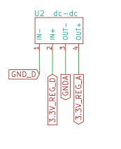
pin 2 connects to N, while pin 3 is NC.  Now check out my schematic:

I have identified two pin 3’s:

NewImage

Curiously, the footprint has the N pin labeled 2 and the NC pin as 3. This is correct, but the schematic botches this….bummer.

Fine.  I messed up.  And that’s why Chris Gammel focuses on bodging in his excellent Contextual Electronics course.  Challenges bring so many opportunities. Here’s an easy one.  Jumper pins 2 and 3.:

NewImage


ChallengesBringOpportunitesOoohhh!  YIPPEE!  The green LED lights up:

NewImage

Here’s the 3.3VDC signal on my scope:

NewImage

There is a 120mV Vpp.  According to the data sheet, the ripple should be ~ 100mV:

NewImage

I should be ok.  Especially since the 3.3V going into the Feather goes through an LDO. 


Ever marching forward…..


(Yet Another) Update to MakeDIgikeyBoM

This is a short post to document an evolution of MakeDigikeyBoM that was necessary to support creating the BoM for the HappyDay Energy Monitor. 

I’m in process getting to the point I can lay out the HappyDay Energy Monitor PCB.  Since I used MakeDigikeyBoM, I’ve evolved the Python I am using on my Mac to an Anaconda install:

Python 3.6.1 |Anaconda custom (x86_64)| (default, May 11 2017, 13:04:09)

Previously, I was using Python 2.7. The version that comes with the Mac OS.

The changes I made:

  • Used Atom instead of Eclipse.  I find Atom easier to work within than Eclipse.
  • Created a new GitHub repo: BitKnitting/MakeDigikeyBOM_Python3.
  • Evolved Python 2.7 to 3 libraries.  I documented some of this.  The rest was done by bumbling through the scripts and getting them to work.
  • Changed method to open a URL.  Using the previous method, Digikey decided my code was a bot.  After a few opens, the Digikey server returned 403 – Forbidden.  My “workaround” is to use a different user agent.  The things I did to fix this:
    • Remove /scripts from the Digikey URL.  As noted by glidud in their comment to my question , “Digikey’s robots.txt signals pretty clearly that they don’t want bots scraping their catalog data. (Edit: At least, they’ve specifically disallowed /scripts/. You may try going directly to a product’s /product-detail/ page.)”    The URL I was attaching the part number to open was previously like this one: https://www.digikey.com/scripts/DkSearch/dksus.dll?WT.z_header=search_go&lang=en&keywords=SI8651BB-B-IS1 .  I changed this to: url = ‘https://www.digikey.com/products/en?keywords=&#8217; + part_number
    • If a 403 was returned, switched to a different browser asking for the request.  I did find out requests assumed to be from a mobile device did not return the info that was needed.  Here is the function (located in makeDigikeyFile.py):
from urllib.request import urlopen, Request, URLError, HTTPError

def getURLpage(url):

    userAgentStrings = [‘Mozilla/5.0 (Macintosh; Intel Mac OS X 10_8_0) AppleWebKit/536.3 (KHTML, like Gecko) Chrome/19.0.1063.0 Safari/536.3’,

    ‘Mozilla/5.0 (Macintosh; Intel Mac OS X 10_10_1) AppleWebKit/536.3 (KHTML, like Gecko) Chrome/19.0.1063.0 Safari/536.3’,

    ‘Mozilla/5.0 (Macintosh; Intel Mac OS X 10_10_4) AppleWebKit/600.7.12 (KHTML, like Gecko) Version/8.0.7 Safari/600.7.12’]


    numTries = 0

    while True:

        try:

            req = Request(url)

            req.add_header(‘Accept-Language’, ‘en-US’)

            # I was getting 403’s – Digikey thought I was a bot.  So if I do,

            # note HTTPError tries again…

            req.add_header(‘User-agent’, random.choice(userAgentStrings) )

            with urlopen(req) as response:

                html = response.read()

                break

        except HTTPError as e:

            logStr = “Denied access: {}.  Reason: {}”.format(url,e.reason)

            logger.info(logStr)

            if (e.code == 403 and numTries < 10):

                logger.info(“Trying again….”)

                numTries += 1

                continue

            else:

                break

    return html

Sacrificial Draft of The HappyDay Energy Monitor Schematic and Layout.

My goal is to install energy monitors in and around my neighbor’s breakout boxes.  Even at it’s simplest install, mucking around within a person’s home electricity is not something people will easily agree to.  One hurdle is the installation.  The HappyDay Energy Monitor PCB must implement the easiest possible installation and maintenance in North American houses. To achieve this, I decided to evolve and adapt Tisham’s Dhar’s excellent work described in the “Thanks to Those That Went Before” section below.

As I write, the Kicad files involved in PCB Layout have been sent to OSH Park. Parts have been ordered from DigiKey. I am excited to solder the chips to the PCB and see how far I can get before I botched something in the design or layout. In the past, it has taken me 3-4 iterations to get a fully working PCB. Certainly, my goal is to take less iterations. However, I do not kid myself into thinking I got everything right for what I call this sacrificial draft. I have learned it is best to finish the design/layout then iterate as soon as possible to understand better what I am doing :-). As far as the expense, it would cost me far more to take a course. Besides, I am not a great learner within a structured environment.

The Goal

The goal of this post is to document what I have learned after finishing the initial schematic and Layout of the HappyDay Energy Monitor PCB. 

Thanks To Those That Went Before

Thanks to Tisham Dhar’s excellent work, I have a firm schematic foundation on which I will build.  Prior work I will explore, evolve, and adapt include:

I have also paid for some consulting time from Tisham which has already had a significant benefit in my knowledge and ability to finish this project.  Tisham has a tremendous amount of knowledge on measuring energy and using the atm90e26.  He is extremely helpful and has the rare ability to clearly explain his choices and concepts.

Open Source

The HappyDay Energy Schematic I reference/am working on is located at this GitHub location.

Requirements

  • Optimize for North American Houses.  North American houses use 3-wire single phase wiring to supply energy to 120V and 240V appliances.  This means the design must accommodate:
    • Two CTs.
    • Two atm90e26s.
  • Consolidate power sources into a circuit breaker.  My current prototype uses two of Tisham’s atm90e26 FeatherWings each with it’s own 120V AC-9V AC transformer.  An additional power source is used for the Feather.  This is messy.  It requires me to run an extension cable from one side of my garage to the other since there are no outlets near our breaker box. Instead, this design will use a 240V circuit breaker to supply energy to the PCB’s ICs.

Schematic

The schematic is separated into two areas:

  • The “main schematic” contains the power circuits.
  • The ATM90_Circuit.sch sub-schema contains the circuits from the power schematic to the atm90’s and Feather (the DC part of the circuit).

Power Circuit

Power Coming From The Grid

As we can see from the diagram below:

OEMPictureElectricityIntoHome

(Image from here)

In our North American homes, 120Vcomes in through two power lines (L0 and L1).  A third line (N) acts as the reference point (analog ground) for voltage/current measurements.  Here is my evolution of the Tisham’s din_power schematic for this part of the circuit:

NewImage

The parts used are noted within the PN field of the component within the schematic.  The reason the rather large 1206 size is used is to get chips that work well in high voltage scenarios.

Clamping Down on Noise

Surges

The MOVs(Metal Oxide Varistors) on L0 and L1 clamp down on the voltage coming in when there are power surges.  Most of the time, voltage in North American homes oscillates from 0 to a peak voltage of 169 volts.  Sometimes this oscillation is disturbed by a spike in voltage caused by a lightning strike or perhaps switching in the power grid:

The ferrite bead clamps down on the high frequency noise that is coming in the N line.

Connecting to the Circuit Breakers

The connector/cable going from the energy monitor to the circuit breakers is modeled after the one used by the Sense monitor:
NewImage                 NewImage
This is why there are 4 pins instead of 3. So that a molex connecter can easily be used.

Voltage Sampling

The Open Energy Monitor project has great info on the how and what of voltage sampling.  The upper part of the voltage divider used to scale the voltage has four resistors in series.  

NewImage


I asked Tisham about this.  He said this way, if any one of the resistors breaks down, the full 120V won’t be sent to the rest of the circuit.  Tisham also noted the resistors need to be rated to handle the incoming voltage (in my case 120V…but to be safe probably 240V rated resistors are a better thing to use).  When building the voltage divider don’t forget the info in the atm90e26’s data sheet.  The pins that are for voltage sampling (15 and 16): …are differential inputs for voltage. Input range is 120μVrms~600mVrms… The maximum reading Vout can be for Vrms is 600mV.

The values for the resistors weren’t entered.  Since 600mV is the highest that can be read, and the lower resistor is 1K, the upper resistors must add up to 199,000 to fit the voltage divider formula:

if R2 = 1000Ω, Vin = 120V, Vout = .6V, R1 = 199,000Ω.  Tisham updated his schematic such that each resistor is 220KΩ 1206 – able to handle at least 240V.  This means the total resistance is 880KΩ…which is a much larger R1 value than I expected.  Tisham noted the requirement for additional head room for measurements. 

DC Power

To get to DC power, one of the L Lines and the N line acts as input into a SMPS.  Tisham’s schematic uses a Hi-Link SMPS.  As I researched SMPSs, I became concerned with the safety of using Hi-Link’s, particularly after reading Skippy’s Random Ramblings.  It will cost me a lot more.  On the other hand, I am hoping to live past this project.

NewImage

(Note: Values for the capacitors come from the RAC03-GA data sheet.)

I picked one that:

  • Outputs a 3.3V regulated voltage.  This way, there is no need for additional LDO’s.  
  • Had passed the “important” safety tests.  I have limited knowledge on power supply safety standards.  I found this Digikey video by CUI Inc. to be helpful.  I chose RECOM’s RAC03-GA.   (Note: Digikey ran out of RAC03-GA’s.  The backorder said they’d have this part in a year from now.  I bet if I sent make to Digikey they’d update.  However, I have not had good luck getting chips in a reasonable time when they are backordered.  I ended up with the RAC04’s.  They appear to be “the same” in key elements The 04 handling 4W instead of 3W and more current.  

Isolating and Connecting AC and DC Grounds

After getting to a circuit that provides regulated +3.3VDC, the circuit plugs into a DC-DC isolator.  This way, the DC power to the Feather does not interfere with the ATM90e26’s measurements.  In addition, the ground potential is set at an equivalent distance.

NewImage

Current Sampling

Two Current Transformers (CTs) are needed to get current readings on the two 120V lines.  The CTs use a TRS 3.5mm audio jack as the connector to the electronics.

The way the ATM90e26 samples current is different than the example Arduino sampling on the Open Energy Monitor web site.  Pins 10 and 11 of the atm90e26 (the current reading inputs for I1P and I1N) are differential inputs.  This means there is no DC bias in a schematic using the ATM90e26.  I ran an LTSpice simulation to best understand the OEM design:

In this simple run, we can see:

  • A Burden Resistor of 33Ω converts the current to a voltage.  The OEM post shows the calculations used to come up with the value for the burden resistor (i.e.: In the picture above, Vpp will be between 0 and 5V).
  • A DC Bias lifts the ADC’s current readings up by AREF/2 (in this example 2.5V).  This way, the negative current values (from the AC circuit) can be measured by the ADC, which measures from 0 to 5V (on the Arduino).
Here is the schematic design I have for the I1N and I1P inputs:

NewImage

The CT plug is a TRS 3.5mm audio jack:

Testing

I started testing using a modified power cord:

NewImage

Voltage Measurement

I started by testing L0_SAMP.  I placed the chips needed to get through this part of the circuit:

NewImage

The biggest challenge I had with soldering the chips onto the PCB was getting the Varistor on.  The chip has a fat plastic body with what I consider to be iddi-biddy pads.  Not only did this make it hard to solder the chip, but also it was easier to “break off” the PCB since the body was far bigger than it’s iddy biddy pads:

NewImage

My goal is to use the least amount of chips to get to a test point.  The first test point is L0 voltage sampling.  Here are the results for L0 voltage sampling using the test points:

NewImage

If I recall, the Vpp fits within the maximum for the ATM90e26 of 660mV.  What I don’t know is how to interpret 456mV…what does this mean? Hmmm…. I’ll get to that after a bit more testing….

3.3VDC

My next test point was adding on the chips that transforms one of the 120VAC lines into a decent 3.3VDC line:

NewImage

Silly me…drat..I ordered two packets of .001µF 1206 high voltage caps instead of one package of .001µF and one package of .1µF.  Undaunted (and perhaps unknowingly stupid of me) I’m going to try an 0805 .1µF for now that I have on hand.

NewImage

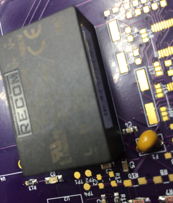
The protagonist in the above shot is the rather large and expensive RAC04-3094-5-ND.  If the circuit is working, the green LED should go on.

FrustratedI put the chips on…and…and…the LED doesn’t light.  Bummer.  
Simpson DOHOn further inspection, I’m pretty sure the break in the circuit was caused by something that I did that in hindsight was incredibly stupid. The holes for the poly fuse are too small.  So I punch bigger holes…and well…cut through the circuit:

NewImage

OKIDOK.  Well, that was fun!  More to follow…..


New! Improved! The Energy Monitor is Running Circuit Python

Tags

This post is about evolving the energy monitor firmware to use Python instead of the Arduino IDE.  It’s been awhile since I discussed the pieces of this project.  Most of this post is about the firmware running on the Energy Monitor.

Here is the “bigger picture” of the HappyDay Neighbors prototype:

The prototyping environment Circuit Python enables makes me smile.  It is for this reason I evolved the environment such that the Energy Monitor:

The Goal

The goal of this post is to run a Circuit Python script on the Huzzah that publishes energy readings to an mqtt broker.  I want to document what I have done to ensure I and others can have the opportunity to not repeat my bumblings or gain a spot of insight that shortens the amount of time to get a prototype out.

Open Source

Circuit Python Libraries

We need access to the ATM90e26 and mqtt.  Here’s how I did it:

We also need Adafruit’s spi_device.mpy

Python Scripts

There is a Python Script running continually on the Huzzah and on the Raspberry Pi.  The Huzzah’s script is using mqtt to publish energy readings.  The Raspberry Pi subscribes to the mqtt messages and then appends them to a local file.

Huzzah

  • The python script running on the energy monitor’s Huzzah is main.py.  NOTE: I don’t like storing my WLAN ssid and password on GitHub.  So to run main.py, there also needs to be a file network_credentials.info in the same directory as main.py.  There is one line in the file:  ssid,pwd:
def init_network():
  full_path = os.path.realpath(__file__)
  dir_path = os.path.dirname(full_path)
  full_filename = dir_path+/network_credentials.info
  ssid =
  pwd =
  with open(full_filename,r) as file:
  for line in file:
  ssid,pwd = line.split(,)
  wlan = network.WLAN(network.STA_IF)
  wlan.active(True)
  wlan.connect(ssid,pwd)
  while not wlan.isconnected():

Stop…STOP!

NOTE: The challenge at this point is stopping the While True: loop so we can fix the code as needed.  The code does nothing to allow us to cut in.  Rather, it runs continually…sleeping for some amount of time and then taking another reading.  When I was trying to access the Huzzah with main.py running using ampy, I got:

ampy.pyboard.PyboardError: could not enter raw repl

What to do? What to do? ( First, I thank @deshipu on Adafruit’s circuit python).

$ screen /dev/tty.SLAB_USBtoUART 115200

ctl-b into REPL

>>>import os

>>>os.rename(‘main.py’,’someothername.py’)

Yippee!  there is no longer a main.py…so now I can get into ampy! 

Raspberry Pi

The Raspberry Pi is running the mosquitto mqtt broker.

This will create and add energy readings to the HappyDay_Readings.csv file in the same directory as the python script.  
 
It is easy to get the CSV file onto another file store by using sshfs.  I discuss how to set up sshfs in this post.

Readings

Here is a link to a Google spreadsheet that contains the readings. A previous post describes taking energy readings in North America and why there are two voltage, current, etc. readings.  This is why there is a v1 and a v2…etc.

That’s It

ChallengesBringOpportunites A very HAPPY time.  It works…. at least for now :-).  Thanks for reading this far.  Please find many things to smile about.


Using mqtt on Circuit Python

Now that I have a Circuit Python library for the ATM90e26, I need an mqtt library.  I didn’t find one within Circuit Python, but I did find Micropython’s umqtt.simple library.  How hard can it be to use the umqtt.simple on the Huzzah to send mqtt messages from a Circuit Python App?

The Goal

The goal of this post is to document the steps I took to send an mqtt message from a Feather Huzzah to a Raspberry Pi.

Open Source

Get umqtt.simple Library Up-n-Running

The umqtt.simple library is located here.   I copied the contents to my local folder as umqtt_simple.py on my Mac for editing with Atom.

MQTT address and port

The DNS name of my Raspberry Pi is ‘raspberrypi.home’ …I found this by looking at the IP addresses in Angry IP.

I had installed the Mosquitto broker on the Raspberry Pi.  To better understand traffic, I started mosquitto in the verbose mode.

  • Stop the currently running instance of Mosquitto:  sudo killall mosquito
  • Restart in verbose mode: mosquito -v


I left the window I started mosquitto in open so I could watch the mosquitto messages fly by.

1509813288: Opening ipv4 listen socket on port 1883.

1509813288: Opening ipv6 listen socket on port 1883.

ooh! Looky looky…port 1883!…I guess this means mqtt connections come in as SSL….

but OOPS….the code in simple.py

if port == 0:
  port = 8883 if ssl else 1883

Isn’t right…so I replaced it with:

if port == 0: ####!!! BUG IN SIMPLE.PY
     if ssl:
           port = 1883
     else:
           port = 8883

Connecting Huzzah to WAN

I seemed to only have to do this once…I would think I should try connecting every time I start an mqtt conversation…I thought this python code was a “nice and robust” way to include connecting to the wifi.

Anywho, I assume you know how to connect to a wireless network with micropython/circuitpython…

import network
wlan = network.WLAN(network.STA_IF)
wlan.active(True)
wlan.connect(’ssid’,’password’) 

Test

I started up the mqtt client on the Raspberry Pi:

 $ mosquitto_sub -t test/test1 -d


I then used ampy to run this small test program (mqttTest.py):

from umqtt_simple import MQTTClient
c = MQTTClient(‘mqtt_client’,’raspberrypi.home’,ssl=True)
c.connect()
c.publish(b’test/test1′,b’hello’)
c.disconnect()

Fix What Didn’t Work

UPDATE (11/5/2017):  uncommented…instead, access umqtt_simple with:

c = MQTTClient(‘mqtt_client’,’raspberrypi.home’,1883)

(Include the port number in the call.  I don’t understand if the Raspberry Pi is using 1883 and NOT assuming SSL?…)

I also had to comment out these lines from umqtt_simple.py:

# if self.ssl:
#      import ussl
#      self.sock = ussl.wrap_socket(self.sock, **self.ssl_params)

Retest

Results from mosquitto_sub:

Client mosqsub/1328-raspberryp received PUBLISH (d0, q0, r0, m0, ‘test/test1’, … (5 bytes))

hello


Log lines from mosquitto -v:


1509818043: Received PUBLISH from mqtt_client (d0, q0, r0, m0, ‘test/test1’, … (5 bytes))


1509818043: Sending PUBLISH to mosqsub/1328-raspberryp (d0, q0, r0, m0, ‘test/test1’, … (5 bytes))


Yippee

ChallengesBringOpportunites  Seems to be working.  Thanks for reading this far….please find many things to smile about.


Porting energyic_spi.cpp (Arduino Lib) to Circuit Python

I’m having the best time with Python.  It is a very easy language to use and it’s interpretive nature makes it a dream to prototype with.

The only thing preventing me from using it on the Feather Huzzah to talk to the ATM90 FeatherWings is a SPI library for the ATM90.  But wait, Tisham wrote a SPI library for the Arduino IDE.  How hard can it be to port the library to Circuit Python?

The Goal

The goal of this post is to document the steps I took to convert the ATM90E26 SPI Arduino library to Circuit Python.

Thanks To Those That Went Before

  • Tisham Dhar (company is whatnick) for the ATM90E26 FeatherWing, supporting Arduino Library, his kindness, and his willingness to share knowledge.  This post is all about porting Tisham’s Arduino library to Circuit Python.  Porting was MUCH easier thanks to having the Arduino Library available.  If not the least to see how funky SPI seems to be on the ESP8266.  For example, the Arduino library sets SPI to MODE2 for the Huzzah…when in reality the ATM90e26 speaketh MODE 3.  This is still weird to me…grrrr…but once I figured out a potential “kludge”, I was able to fix my challenges with SPI…although I also got help from my next person I am incredibly thankful to:
  • Scott Shawcroft (aka tannewt)…I’m bumbling around trying to get the SPI gunk to work with Circuit Python.  I go to Adafruit’s Circuit Python Discord Chat…I ask a question that is stumping me.  Scott takes several (several) minutes to help me figure stuff out…and….SHAZAM… the SPI stuff falls into place.  During the debugging process, Scott was incredibly sharp, helpful, and kind.  Which gets me to my next round of thanks..
  • Tony Dicola I learn A LOT from Tony’s tutorials and videos.  The particularly useful tutorial for this post: Porting an Arduino library to CircuitPython: VL6180X Distance Sensor.
  • Adafruit – THANK YOU for the community you have built, the hardware and software that I seem to constantly crave.  I can only hope more companies see you as a role model for how to run a successful, community driven company that focuses on the positive.
THANK YOU THANK YOU THANK YOU THANK YOU THANK YOU THANK YOU…..THANK YOU…..AND MORE THANKS TO YOU…..

Open Source

    • HappyDay_energyic_spi.py : Circuit Python library for the ATM90e26…the protagonist of this post.
    • PyspiTest.py : Lil’ test app.  It imports HappyDay_energyic_spi.py and calls into the functions … like getSysStatus() ….

Stuff I Did

Install Circuit Python on a Feather Huzzah

Here’s what I learned from installing Circuit Python:

1. Use the esptool to erase the Huzzah’s flash and install Circuit Python.  I didn’t have this on my Mac, so from a terminal window…: $ pip install esptool

 Now that I had the tool that knows how to r/w the Huzzah’s flash, I needed to know the serial port the Huzzah was connected to.  From a terminal window….$ ls /dev/cu*

2.  PRACTICE SAFE FLASHING…START BY ERASING.  Sorry for shouting but I wandered down a gnarly pit before I practiced erasure.  By gnarly pit, I changed wifi’s and Circuit Python was NOT happy…Circuit Python would continually loop:

File “inisetup.py”, line 9, in wifi
OSError: can’t set AP config 


Adafruit CircuitPython 2.1.0 on 2017-10-17; ESP module with ESP8266
>>> scandone
no <SSID name> found, reconnect after 1s
reconnect

From a terminal window….

$ esptool.py -p /dev/cu.SLAB_USBtoUART erase_flash

3. Get the copy of Circuit Python from  Adafruit’s GitHub location that holds Circuit Python releases.  I renamed the binary to a simpler name (huzzah.bin)

4. Jumper GPIO0 and GND so the ESP826 is in boot mode.

5. From a terminal window…  $ esptool.py -p /dev/cu.SLAB_USBtoUART –baud 460800 write_flash –flash_size=detect 0 huzzah.bin

Check Install

Easiest way I found to check install was to go into REPL: 

$ screen /dev/tty.SLAB_USBtoUART 115200

OKIDOK.  Got the >>>

All is well.

Get ampy Going

Unfortunately, I can’t do a USB mount on the Huzzah.  I ended up using the  ampy tool.  I used this convenient tool to copy my Python library code to the Huzzah as well as run my test app.

Note: I didn’t do this but:

If you don’t want to constantly specify the –port option you can set the AMPY_PORT environment variable in your terminal session and ampy will use it as the board’s serial port.

$ export AMPY_PORT=/dev/tty.SLAB_USBtoUART

Write Python Library

The ATM80e26 Circuit Python library is called HappyDay_energyic_spi.py.  I’m not going to explain the code because not only is it similar to the Arduino library, Python code seems easy to understand.  Beside, you write better Python code than I do.

Resources

$ ampy -p /dev/tty.SLAB_USBtoUART put spi_device.mpy  /lib/spi_device.mpy

(after creating the /lib directory using amp’s mkdir command) 

Note: Library files go in the lib directory because it’s part of the Python path by default.

Adjust the Voltage Gain

THIS IS IMPORTANT.  I discuss adjusting the ATM90c26 voltage gain to a specific setup in this post.


Figure out SPI Gobly Gook

By “Gobly Gook” I mean the SPI phase and polarity.  Now I got (ok, perhaps totally) confused on this.  The Arduino library sets the SPI Mode for the Huzzah to Mode 2.  But, the ATM90e26 speaketh in Mode 3.  Grr…

NewImage

From the data sheet (4.1): Data on SDI is shifted into the chip on the rising edge of SCLK while data on SDO is shifted out of the chip on the falling edge ofSCLK.

Bytes from the ATM90e26 Meter Status Register

The Meter Status Register is:

#define EnStatus 0x46 //Metering Status

The SPI section of the data sheet notes (section 4.1.1/Read Sequence) notes the high bit of the MOSI request is set to 1 when asking to read a register.

0x46 | 1 << 7 = 0XC6

Read Meter Status Register Request 

MOSI == SDO (Master Output —> Slave Input) -> Falling Edge: E.g. MOSI byte: 1100 0110 = 0XC6 

ArdspiTestMeterStatusMOSI

Image on Imgur 

Data Returned From ATM90e26 

MISO == SDI (Master Input <— Slave Output)  -> Rising Edge E.g. First MISO byte: 1100 1000 = 0XC8

ArdspiTestMeterStatusMISO

Image on Imgur 

Set up The Init Function

This led me to:

def __init__(self,spi_bus,cs):self._device = SPIDevice(spi_bus,cs,baudrate=200000,polarity=1,phase=1)

I set the baud rate to what the Arduino library had… then there is the polarity=1, phase=1 (i.e.: SPI mode 3).

Figure Out the GPIO Naming

As you can see in the PyspiTest.py test app,  board pins are used to set the CS:

cs = digitalio.DigitalInOut(board.GPIO0)

before creating an energyic_SPI instance.  i.e.:

>>> import board

>>> dir(board)

[‘ADC’, ‘GPIO16’, ‘GPIO14’, ‘SCK’, ‘GPIO12’, ‘MISO’, ‘GPIO13’, ‘MOSI’, ‘GPIO15’, ‘GPIO2’, ‘GPIO0’, ‘GPIO4’, ‘SDA’, ‘RX’, ‘TX’, ‘GPIO5’, ‘SCL’]

Run The Test App

s margaret$ ampy -p /dev/tty.SLAB_USBtoUART run <python test program..>

Here are results that I got without using a CT or power calibration.  It’s the same results I received when I ran the Arduino library:

Checksum 1:4A34
Checksum 2:D294
Sys Status:0
Meter Status:C801
Voltage:0.03
Current:0.01
Active power:0.00
p.f.:0.00

That’s It

ChallengesBringOpportunites  YIPPEE!!! IT WORKS.  Thanks for reading this far.  Please find many things to smile about.


It Works! Monitor Energy Use

ChallengesBringOpportunites  Yippee!! I clamped the CTs on the incoming power cables:

Pasted Image 10 26 17 4 27 PM

Attached the CTs to the Energy Monitor:

IMG 6330

Plug in the 9V AC Transformers:

IMG 6331

Get the Raspberry Pi to collect the data and create a visualization:

Pasted Image 10 26 17 4 35 PM

I compared results to the readings I get from the Sense monitor.  The Sense monitor’s readings are typically about 70 watts more.  A 70 watt difference seems “good enough” for me.

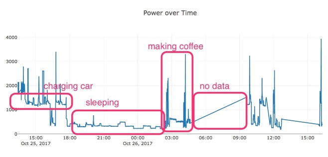
As I mentioned in a previous post, I used Dash (plotly) to visualize.  While the current visualization is ugly/course, it is a great start with very little code required.  Just by using Dash/plotly, I’m able to zoom into sections of the plot and get the value of individual data points:

NewImage

I zoomed into the area of the plot which monitored energy use while I was making coffee.

It is exciting – and a relief – to get to plotting power readings.  There’s some stuff I need to do before I install into my neighbor’s breaker box…but this is a nice milestone.