Tags
This post is about figuring out how much -V is being delivered by the charge pump IC to the op amp IC I used I used in the pH Circuit I breadboarded in an earlier post.
The Goal
The goals of this post include:
- knowing the -V rail to expect for the op amp I use in the breadboard pH circuit.
- gaining a solid understanding of AC Coupling as it applies to detecting AC noise coming from the Vout of the Charge Pump. I cover the Charge Pump and its pins in this post. The V(out) of the Charge Pump is used to provide -V to the op amp in the pH circuit such that negative pH signals can be read.
- deciding if the pH circuit needs to evolve to reduce the AC noise that is attached to the V(out).
Thanks To Those That Go Before
These folks have made a tremendous positive impact helping me learn the electronics concepts and practicalities that I needed to complete this prototype of a pH circuit.
- @SparkysWidgets – His phSensor schematic and blog post is all you need to get started. Because I lack the background in electronics, I didn’t understand much of the post at first. This got me writing out what I learned here. This person has been exceedingly thoughtful and open with his knowledge. Kindly (and I assume patiently!) pointing me in the right direction. Please consider supporting his efforts.
- Chris Gammell – our very knowledgable and gifted instructor of Contextual Electronics. A course I would highly recommend if you are interested in turning your prototypes into PCBs and learning tons about electronics along the way. Chris’s teaching style is exceptional. He teaches more like a knowledgable guide. He does first what he expects us to do, examines his mistakes, and constantly seeks and uses feedback from his students. Chris is exceptional. His efforts are another I highly recommend support in
- Gabriel Anzziani – the creator of a very nicely done oscilloscope for the price. This is the first time I used a scope. I admire Gabriel’s ability to keep a tool simple. THANK YOU!
Debugging Tools
- Oscilloscope – I continue to use theXminilab XScope.
- DMM – I am using an EXTech330. Chris recommended this DMM for Contextual Electronics.
- Breadboard, MAX1044, wires, resistors, capacitors, Arduino Uno providing 5V regulated power supply.
Test Scenario
To measure the amount of AC noise coming from the V(out) of the MAX1044, I disconnected the TL072 op amp from the MAX1044 on the pH circuit in order to isolate the Charge Pump from the Op Amp.

I then measured the Voltage . The intent with adding the resistors was to add: no load, around 5mA load, and around a 10mA load. These current values were chosen because the spreadsheet notes:
They deliver 10mA with a 0.5V output drop.
The words in this sentence lead to potentially different interpretations. I assumed:
- “They” means the MAX1044
- “deliver 10mA” means UP TO 10mA
- “with a 0.5V output drop” means any load will cause the voltage output drop to be .5 V. Thus, the maximum value for -V(Out) = power source voltage – .5V. Meaning a perfect Arduino Uno 5V source allows a -4.5V rail. In a breadboard prototype the 5V source varies a bit in value – typically from 4.8 to 5.02, so the -V(out) will also vary by this amount.
-V(out) Measured Results
| Measured | Expected | Measured | ||
| R | I | I | -V(out) | Arduino V |
| 470 | -0.00745 | -.00796 | -3.74 | 4.96 |
| 510 | -0.00759 | -.00788 | -4.02 | 4.96 |
| 1000 | -0.00437 | -.00444 | -4.44 | 4.98 |
| 2200 | -0.00211 | -.00215 | -4.72 | 4.98 |
I had a set of resistors I’d gotten earlier. Convenient values to measure included 470Ω, which at 5V has a current of close to 10mA. As well as 1K, 5mA at 5V. Based on the data sheet’s statement: They deliver 10mA with a 0.5V output drop.
I saw a drop of 1.22V with a 470Ω resistor and .94V with a 510Ω resistor. -V(out) gets closer to the Arduino’s 5V input power as the current is lowered. When the resistor was 1K – which is about the load of the op amp at 5mA – the measured v(out) was -4.44 a voltage drop of -5.4 volts – in close range to: They deliver 10mA with a 0.5V output drop.
I am not sure why the -V(out) is not at the .5V drop for 470Ω and 510Ω. I am not concerned for the pH circuit since the signal range is +/-.414V – well within the -V(out) range.
I then measured the -V(out) when the MAX1044 is connected to the TL072 and the scope is inputing an AC signal of +/- .414V. The Voltage source (Arduino) measured 4.92. I measured -V(out) to be -4.34, a difference of .58V – close to the .5V drop noted in the Max1044 data sheet. This result seems to be within the range of the expected.
Now I’ll move on to measuring the AC noise on the -V(out) line.
On to AC Noise
Since this is the first time I have measured AC noise, I’m documenting what I did/learned on this process.
How I measured AC Noise
When I first looked at the -V(out) signal coming out of the MAX1044, I didn’t see any noise on the scope. It turns out it can’t be seen on the scope because the DC signal is hogging up the display and shifting the frequency (y axis). This seems totally rude to me…but..how to shift the focus back to the AC frequency? The focus on the DC frequency is referred to a DC bias. In order to analyze the AC noise, the DC signal needs to be removed from the scope’s probes. A simple way to remove the DC signal so that I can look at just the AC noise is to use AC coupling.
To measure AC noise I will use the Xminilab oscilloscope.
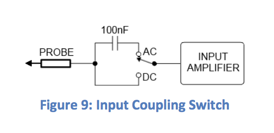
The Xminilab does not have AC Coupling built in. I’m glad it didn’t because it gave me the opportunity to get a hands on understanding of what AC Coupling is by building a simple DIY AC Coupler. Chris figured this out and showed us how to do it in a Contextual Electronics segment. Here is an image from the scope’s manual:

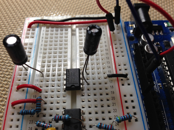
Ah – yes…use a capacitor to filter out a signal. So we all set about and built our AC Coupling “dohicky” which takes the place of the switch. Here’s mine:

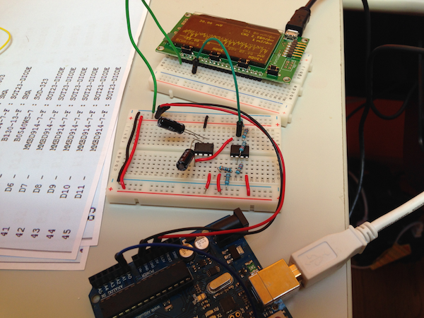
To get closer to how the circuit will be used, I used the AWG of the Xminilab to add a sine wave as input to the TL072 op amp’s pin 3. Then I put the wires of the DIY AC Coupler on -V(out) of the MAX1044:

And…no need to wait for it…a YIPPEE MOMENT! I could now see the AC noise on my scope:
I measured the frequency of the AC signal to be 2.7KHz,

a high frequency when compared to a 1Hz pH signal’s frequency.
The ∆V =.165V,

3.7% noise when the -V(out) is -4.34, as measured earlier.
I can think of the following ways to lower the signal noise added by the MAX1044:
- use a larger capacitor than the 10uF connected between -V(out) and GND
- use the MAX1044’s BOOST mode. The data sheet notes: Connecting BOOST to V+ increases the oscillator frequency by a factor of six. I’m thinking what this means – please let me know if I am wrong – is the MOSFETs in the MAX1044 will open/close at a faster frequency when BOOST is connected into the circuit. The increased frequency will cut down on AC noise.
| ∆V – no BOOST | ∆V – BOOST | |
| 10uF | 0.12 | 0.06 |
| 47uF | 0.05 | 0.05 |
| 470uF | 0.025 | 0.025 |
Conclusions
I have increased my ability to design a more robust circuit by knowing how to analyze AC noise. As Chris pointed out to me, even a small amount of noise will cause significant errors in reading. Particularly since the pH signal has a small amplitude of +/-.414V. Changes I plan to make in the pH circuit to minimize AC noise include:
- using the BOOST mode of the MAX1044
- increasing the capacitor located between -V(out) and GND from 10uF to around 500uF
By making these two adjustments, the ~ 2.6% AC noise of the =-V(out) decreases to ~1.3%. Adding a higher capacitor should further eliminate the AC noise to ~ .56% based on the measurements I made. While this is a “one of” measurement on a bread board prototype and every PCB/chip arrangement will vary the results, the general take away I have is to use BOOST mode and a larger capacitor to lower AC noise in the pH signal circuit.
What’s Next
I’m going to let my new found conclusions stew a few days before I update the pH circuit schematic. Maybe my conclusions are ill-informed. I am hoping one of you kind readers will point out assumptions or test methods I used that caused me to make incorrect conclusions. After a few days I will update the pH circuit schematic. I need to keep making progress on building the BenchBudEE, our project in Contextual Electronics. Wow – I’m learning A LOT about soldering PCBs. Another “learn by doing” I am happily lapping up is following the values of a sub-circuit as a solder on more parts. For example, I’ve been following the schematic for the +12V, adding C’s, R’s, inductors, POTs, LM317 and LM337…after each addition, I check what voltage I get and compare it to what I expected to see. It is the first time I have a strong look at reading the schematic, comparing that to the board layout, and then checking out the values on the actual PCB! What an amazing experience. The other great part here is seems to me that most folks taking the course are more advanced than me. I LOVE being the least educated/skilled – I learn more and I am lucky that my classmates exuberantly share their techniques. Chris did a great job setting up the collaborative environment to enable this incredible feedback. I also want to make progress on the EC circuit.
